01
Capture strategy
Scanner positions are planned around the required surfaces, expected occlusions and level of detail.
 Canopus Innovation
Technology & accuracy
Live capture / 360°
Status: recording
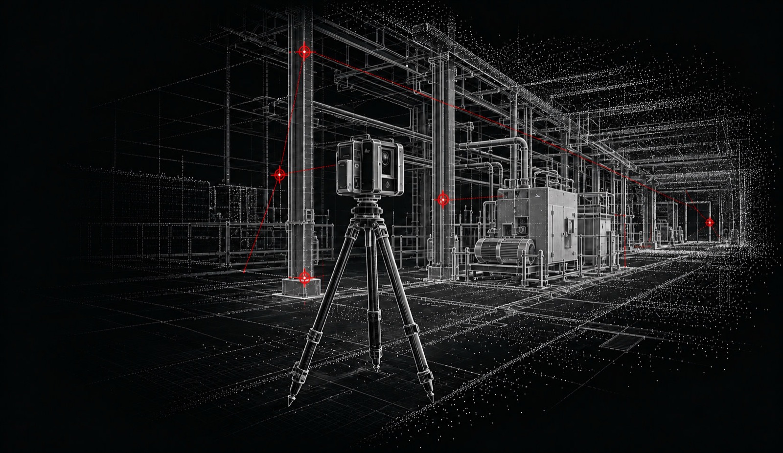
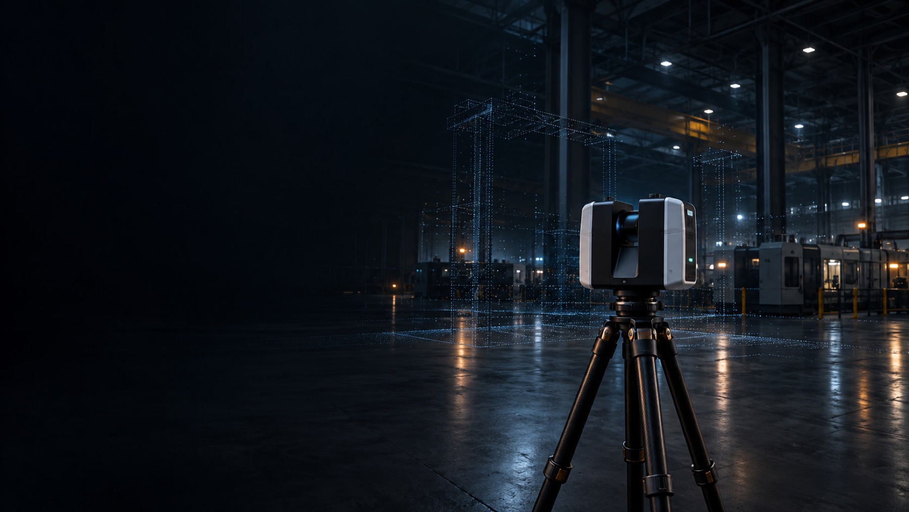
The Leica RTC360 captures the site. Our scan planning, registration, verification and delivery workflow turns that capture into a reliable spatial reference for design, fabrication and installation.
How data is built
Instrument specifications matter, but they are only one part of the result. Scan-to-scan distance, line of sight, surface overlap, site movement, control and registration all influence the quality of the final dataset.
We define what the data must support before mobilisation, then design the capture and verification method around that decision — whether the requirement is a general facility layout, an equipment fit-check or measured installation interfaces.
01
Scanner positions are planned around the required surfaces, expected occlusions and level of detail.
02
Adjacent stations share sufficient geometry so successive setups can be combined into one consistent site model.
03
Targets, known coordinates or survey control can be introduced when the project coordinate framework demands it.
04
Registration, coverage and project requirements are reviewed before modelling, comparison or handover begins.
From the field

Accuracy is scoped
Using the Leica RTC360, we capture millimetre-level 3D data. Leica specifies 3D point accuracy of approximately 1.9 mm at 10 metres, 2.9 mm at 20 metres and 5.3 mm at 40 metres. Final project accuracy also depends on scan distance, overlap, site conditions, registration and the required deliverable. Before mobilisation, we define the target tolerance, plan the scan positions and survey control, and verify the registered dataset before delivery.
1.9 mm
3D point accuracy at 10 m
2.9 mm
3D point accuracy at 20 m
5.3 mm
3D point accuracy at 40 m
2M
Maximum points per second
Published Leica RTC360 3D point accuracy. Final registered project accuracy is verified against the agreed tolerance before delivery.
What changes the result
01
Published tolerances are expressed at representative working distances rather than treated like distant building structures.
02
Laser scanning records visible surfaces. Additional positions are used to cover occluded machinery, guarding, interiors and congested aisles.
03
Moving people and vehicles, vibration, dust, reflective finishes and transparent materials can affect coverage or create noise that must be managed.
04
Individual scan stations overlap, are aligned, and where required connected to control in an agreed project coordinate system.
Registration & quality control
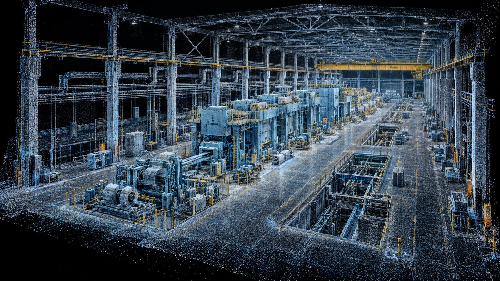
The field capture is processed so a series of stations become one site model. Overlapping stations are aligned, the registration is reviewed, unwanted clutter is removed and the dataset is prepared for the agreed deliverable set.
Measured geometry
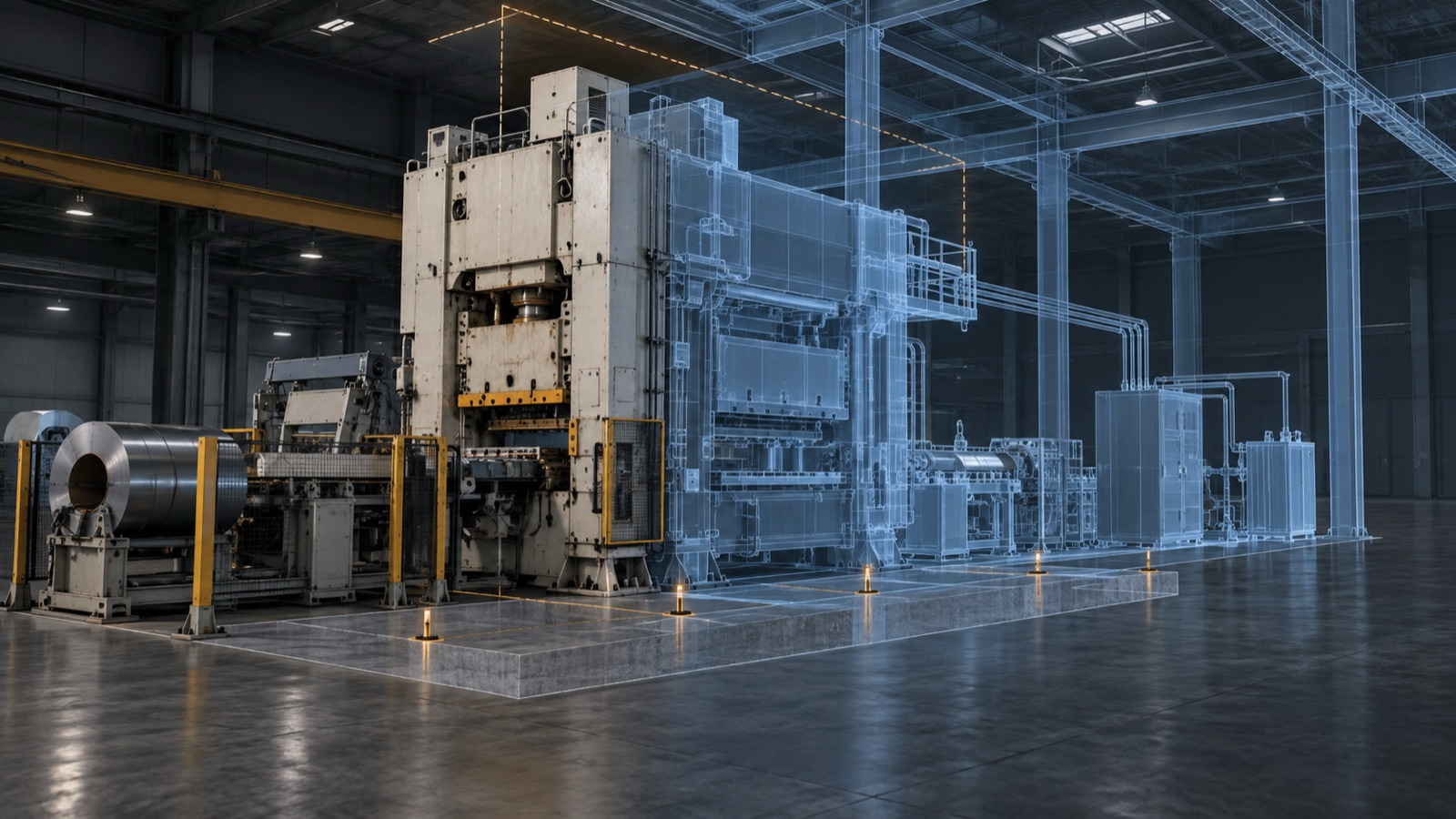
A point cloud is a dense record of visible surfaces, not an X-ray of the facility. Understanding that boundary is part of planning a useful survey.
Deliverables & file formats
The output is defined around viewing, drawing, modelling and comparison workflows your project team already uses — not a proprietary viewer they have to learn.
| Deliverable | Format | Used for |
|---|---|---|
| Registered point cloud | E57 · PTS / PTX | Software-independent measured data for viewing, measurement and downstream processing. |
| Autodesk scan project | RCP / RCS | Registered scan project for compatible Autodesk design and coordination workflows. |
| 2D as-built documentation | DWG · DXF · PDF | Dimensioned plans, elevations and sections extracted from measured conditions. |
| 3D engineering model | STEP · IGES · native CAD | Accurate built geometry for layout, clearance, interfaces and fit-check work. |
| BIM / coordination model | IFC · NWD / NWC | Shared geometry for architecture, structural and MEP coordination when needed in scope. |
| Visual site reference | 360° panoramas · stills | Photographic context for teams reviewing the facility away from site. |
Planning questions
Define the requirement
Share the site, the intended decision, the required outputs and any known tolerances or coordinate requirements. We will define the capture and verification around that purpose.
Office
Am Ohlenberg 19, 64390 Erzhausen, Germany
Hours
Monday–Friday: 8:00 AM–5:00 PM